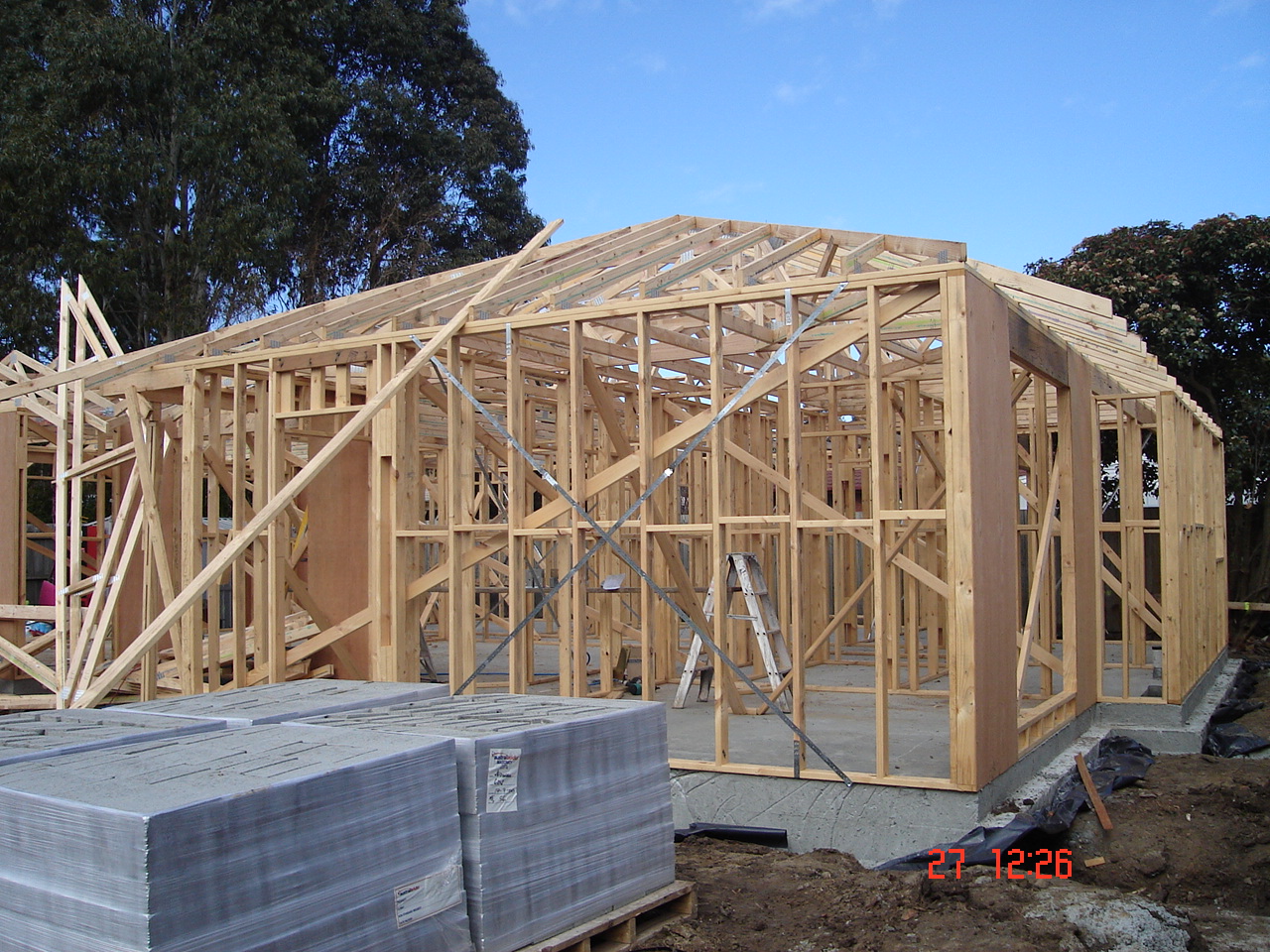
Wall Frames
Our prefab wall frames are designed in accordance with Australian Standard AS1684. Our frames are manufactured from MGP10, MGP12 & F17 KDHW graded timber, which is used for our studs and lintels. Our openings are double nogged either side for extra stability, and door opening studs are extended past the bottom plate, eliminating the small bottom plate which can split when fixing in your door frames.
Our ply bracing is of the highest rating as well, utilizing 4mm F27 ply as standard wall brace. Top & bottom plates are fixed with 100mm nails, with our noggs being 70mm so as not to protrude past the edge of the stud. All our frames are manufactured on jigs that allow us to square the walls off, which saves time on installation, and in turn puts more money back in your pocket.
All our frames are designed with 2/90×35 Top plates and all load bearing studs at 450mm centres. All work can be designed to suit your own particular requirements, so be sure to fill out the relevant details on our Contact form to ensure we are working to your specifications.
Benefits of Prefabricated Timber Wall Frames
Prefabricated timber wall frames offer many of the benefits associated with timber roof trusses. Furthermore a combination of timber frame and lightweight cladding can deliver further benefits including reduced costs, improved energy efficiency and a greater contribution to sustainability.

Components of a Timber Wall Frame
a. General benefits of Prefabricated Timber Wall Frames
(i) Cost effectiveness
Prefabricated timber wall frames are manufactured off-site in a factory environment using state of the art software and manufacturing equipment, and are delivered to site ready to install with clear installation instructions. The reduced on-site erection times lead to significantly reduced labour costs. Prefab frames can also reduce the effect of wet weather delays.
Frames are individually detailed and engineered which optimises the timber components to suit the design loads applied to them.
Manufacturing of frames optimises timber stock, leading to minimisation of timber waste versus the on-site stick built alternative.
(ii) Piece of mind for building authorities and certifying engineers
As part of a fully engineered system, Etruss Solutions will ensure that the critical studs, wall plates, lintels (timber) and various tie downs and restraints are designed to support the roof and upper storey loads. More importantly, the ‘right hand is guaranteed to be talking to the left hand’ with one entity (Etruss Solutions) overseeing the design and manufacturing of the entire frame.
iii) Versatility of timber during construction
Timber is a material that all builders are familiar with and comfortable using. This provides for flexibility on site when foundation errors exist or last minute changes are required.
(iv) One-stop-shop solution
Etruss Solutions can provide builders with their complete roof, floor and wall framing requirements as part of a fully engineered system including lintels and beams.
b. Benefits of Prefabricated Timber Wall Frames with Cladding
Many builders in Australia are moving towards the construction method of timber frames with cladding, as a result of increased pressure for faster and more affordable building methods.
(i) Cost Competitiveness
Using James Hardie cladding or weatherboards for example, provides flexible design options with a host of other benefits. In James Hardie’s The Smarter Construction Book they conduct a study on ‘What’s the Cost of Your Wall?’ The research reveals that fully clad lightweight homes are generally just as cost competitive as the brick veneer ones. They are particularly competitive when compared to brick veneer with applied finishes or double-storey houses. In fact, using texture-coated and painted HardiTex base sheet is 80% of the cost of face brick veneer for a single storey home, and even less if the brick is rendered.
Using heavy weight materials in set-back upper storey construction usually means using more structural steel than if the upper wall was built using lightweight materials. Using lightweight cladding materials can potentially reduce the structural steel, lintels, scaffolding and therefore painting costs. Other benefits include:
(ii) Fewer Trades are Required
When building with cladding and weatherboard products, the only people you need are the carpenter and the painter. It also reduces the issues associated with wet weather when bricklayers prefer not to work in these conditions.
(iii) Streamlined Construction Process
The streamlined construction process and fewer trades are also a big speed driver. Block or brickwork introduces sand, cement, scaffold and waste with the associated logistical complexities, particularly on tight sites in medium density areas.
(iv) Simple Installation
Instead of laying bricks, rendering, scoring and painting – with all the associated mess and scheduling of different trades – cladding achieves this look without the fuss. It is a simple installation method.
(v) Thermal Ratings Are Easily Achieved
Framed construction and lightweight cladding can make it easier to achieve the necessary thermal ratings for the Perth climate.
(vi) Environmental Benefits
The environmental effects of building huge houses that use vast amounts of energy are measurable and alarming. Embodied energy is the energy consumed by all of the processes associated with the production of a product. CO2 emissions are highly correlated with the energy consumed in manufacturing building materials. The embodied energy of a fibre cement clad timber-framed wall systems can be up to 60% lower than a clay brick veneer wall.

AS1684 Bracing Details
|
AS 1684.2 Section 8 (Bracing)
Bracing is required to withstand the wind pressure on the timber framed structure. The wind produces a lateral load, which must be transferred through the structure to the foundation. The ceiling and floor form a horizontal diaphragm. The wind force is transmitted through the ceiling diaphragm to the bracing walls, which transmit them to the floor structure as indicated in the figure below.
The ceiling and floor diaphragms play important roles in the transfer of wind loads from the walls and roof to the braces. The ability of a ceiling or floor diaphragm to effectively transfer the wind load depends on the depth of the diaphragm. Narrow or long diaphragms will not transfer the wind loads as effectively as a deeper diaphragm. The smaller the depth to length ratio the more effective the diaphragm. For this reason the spacing of bracing walls in limited as per Clause 8.3.6.7.
8.3 Wall and subfloor bracing
Bracing shall be designed and provided for each storey of the house and for the subfloor, where required, in accordance with the following procedure: (a) Determine the wind classification The maximum design gust wind speed must be known to determine the forces acting on the building. According to AS 4055 Table 2 the wind classifications for Regions A and B is N1 to N6. The wind classification will always be stated in the specifications.
8.3.4 Racking force
The racking force of the building shall be determined by the method (A area of elevation) or by the method (B simplified) given in Appendix G
Method B (simplified)
Using Method B you do not require the area of elevation. The tables G1 to G4 for the various wind classifications differentiate between a) gable hip & ends and b) long length of building
The width is required because the diaphragm depth is smaller for the length of the building (refer to diagram above). These figures need to be multiplied by the length of the building to obtain the racking force for the length of the building. Example 1, length of building 13.5 m, width = 8.5 m, roof pitch = 26°, wind classification N3.
Use Table G3 (C) (single or upper storey) Wind Classification N3 (see below) to determine the raking force for the Length (long side) of the building
Therefore the racking force is 13.5 m × 5 kN/m = 67.5 kN
Using interpolation 13.5 × 4.52 = 61.02 kN (reduction of 9.04%)
If you are prepared to calculate the area of elevation then the racking force will be smaller. Compare this with the figure below.
Method A (area of elevation)
Using this method you need to calculate the area of elevation to determine the racking force. Table 8.1 to 8.5 include the pressure in kPa (kN/m²) for various roof pitches. Note 3 of Figures 8.2 (A, B & C) states
Area = 13.5 × 2.7/2 + (13.5 + 5)/2 × 2.07 = 37.37 m²
Example 2: Using the same measurement as in the previous example. Given an area of elevation of 37.37 m², length of building 13.5 m, width = 8.5 m, roof pitch = 26°, wind classification N3.
Refer to Table 8.2 below to determine the racking force
8.3.6.3 Structural wall bracing
Structural wall bracing is purpose-fitted bracing, being either sheet or cross-timber or steel bracing.
Table 8.18 gives the specific capacity for each metre length of various structural bracing types. 2700 mm high max. The table caters for different types of wall bracing (timber and metal angle braces, double diagonal tension or metal strap braces, plywood sheet bracing etc.) The bracing capacity is indicated in kN/m. To find out how may metres of bracing is required you need to divide the total racking force by the capacity of each bracing type. According Table 8.18 the bracing capacity bracing type (b) is1.5 kN/m
Using the figure from Example 2
There may not enough walls (external and internal) to accommodate 27.41 m; therefore another type of bracing should be selected. Plywood bracing according to Table 8.18 (g) has a bracing capacity of 3.4 kN/m
The bracing should be evenly distributed. Sheet bracing walls shall be a minimum of 900 mm wide to satisfy the requirements of their nominated ratings (Claus 8.3.6.3 & 8.3.6.5). The max. spacing between braced walls at right angles to the building length or width shall not exceed 9 metres for wind classification up to N2. For wind classification greater than N2 refer to Table 8.20 & 8.21 (Clause 8.3.6.7).
8.3.6.2 Nominal wall bracing
Nominal wall bracing is wall framing lined with sheet materials such as plywood, plasterboard, fibre cement or hardboard, or the like, with the wall frames nominally fixed to the floor and the roof or ceiling frame.
All sheet materials have a potential bracing capacity. Their capacity (strength) relies heavily on the fixing method used to attach it to a wall frame.
Below is an example of bracing distribution
Check even distribution and spacing Check connection of bracing to roof/ceilings and floors
Use the same principle to indicate the bracing for Plan E Wall Bracing – Structural. |
||||||||||||||


